build log

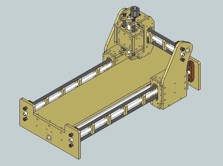
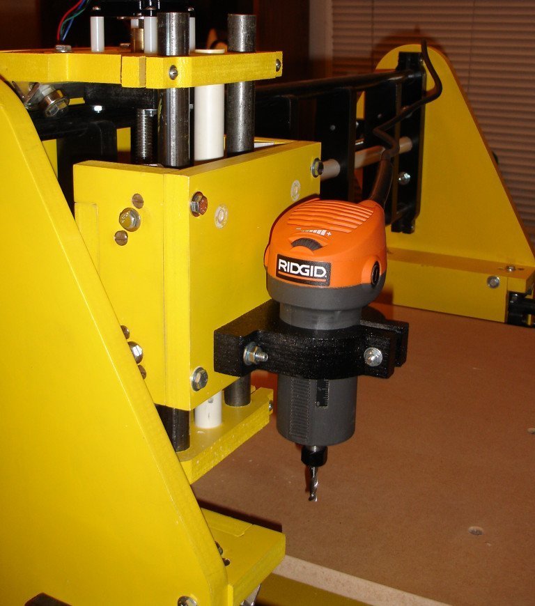
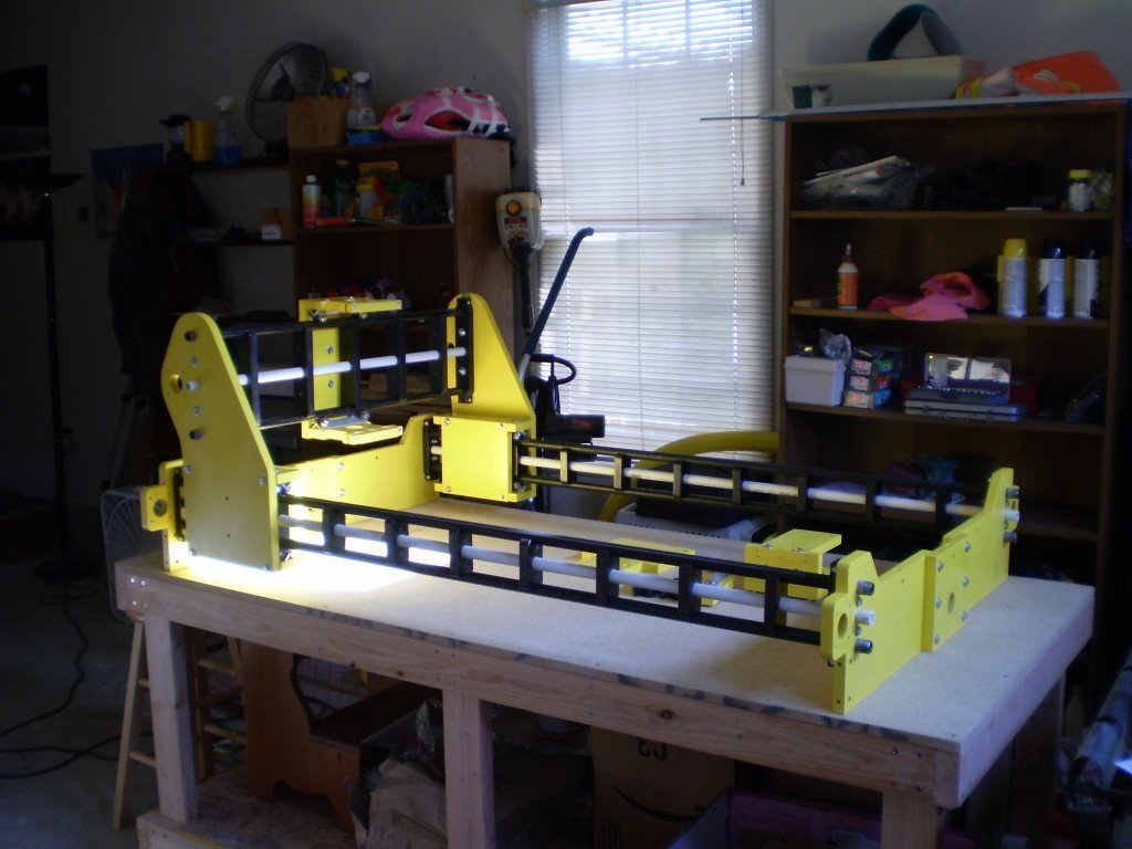
Clamping and first run of the BS1v2

Well it’s done… well as done as any DIY CNC can be. I really only had to solve the clamping issue and figure out what to cut the last time I posted. The clamping issue was solved by drilling a pattern of holes in the table that I thought would cover most thing I would be cutting (size of material) and using T-Nuts to provide a place to bolt down some simple brackets.

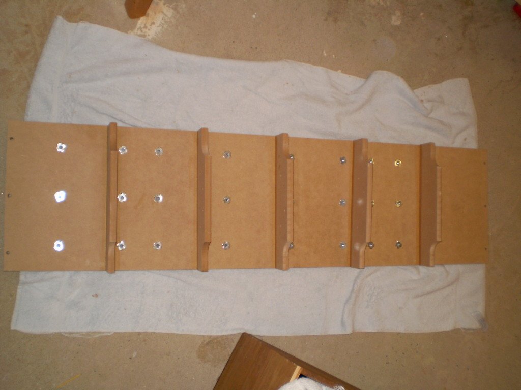
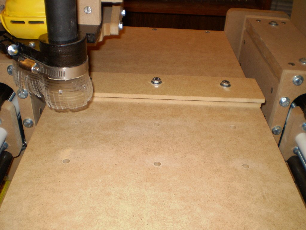
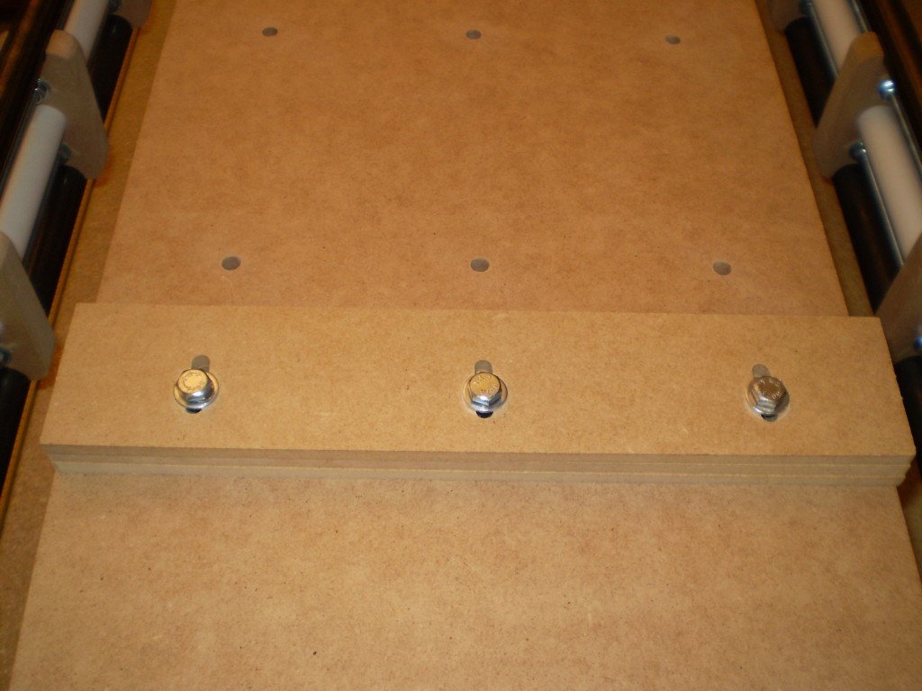
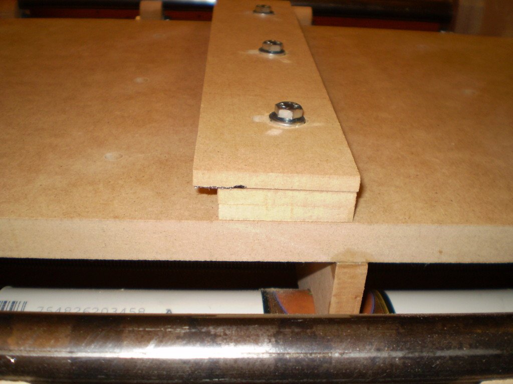
The brackets are made of 1/4″ MDF and you basically adjust the height by adding or removing pieces to match the height of the material, I plan on cutting some 1/2″ and 1/8″ pieces to give me a bit more flexibility in matching different material heights. They worked fairly well, but I am going to add a small lip to them to provide a bit more bite so I won’t have to tighten them down so hard to get a good hold.

The next thing I needed was something to cut, however since I am not starting a new machine (yet), I was at a loss. My wife came to my rescue by asking if I could make a a replacement part for the Jenga game my kids got for Christmas. The original version of the game came with a nice plastic sleeve to help set the game up, but the newer versions come with a cheap and fairly useless cardboard sleeve. A few quick measurements and 15 or so minutes in CadStd yielded a nice replacement, and my first cut video.

I am in the process of cleaning up the cad files a little bit, but my next post be about releasing them to public, just need to figure out what license to use. I am also trying to convince myself that I want to offer kits, but I am apprehensive of such a commitment of my time.  Maybe I’ll have it figured out by the next post.

6 Week Progress Report

So right after the last post I did a bunch of work in about two weeks and was to the point were I was just about ready to run, and then nothing…  this update has been sitting in draft mode for 2 weeks so I decided to force myself to finish it tonight, so here we go.

The first thing I decided I needed to do was to wire up and test the surplus motors I bought.  I used  22ga  4 wire security system wire I found out home depot, I used this wire on my two previous machines without any issues.  Using the documentation over at the Lin Engineering site, I was able to easily wire the motors up as bipolar parallel.

Then with a bit of remorse, I reclaimed the electronics from the Rockcliff Mini Model D, removed the extra parts (4th Axis – Probotix side step and MDFLY breakout board) and wired it all up to the remaining Xylotex 3 Axis controller.  After making the necessary changes to the EMC2 configuration, I ran a few quick tests and everything just worked… this is the first time that has ever happened, but I guess 3rd time is a charm after all.

Let it Begin… Let it Begin!!!

Hard to believe it’s been two months, but the holidays are crazy and the cold set in a bit sooner and harder than is normal for Georgia, so my days in the garage have been sparse (I know excuses, excuses…). But I have made good use of the time I have had and I am happy to announce that all of the parts are cut, drilled (~100 cross dowel connections), and ready to assemble.

This is my first time going from a 3d drawing to a physical machine, which very exciting for me. I expect things should move relatively quick from this point on, since I believe I have everything else I need. I may decide to buy some new motors rather than pulling the ones off the Rockcliff Model ‘D’, as they are only 116oz and I was planning on putting 2 on the X axis to handle moving the gantry, it would be a lot easier with just 3 more powerful motors.

Hopefully I will make enough weekly progress to make posting worth while, this should not take more than a month even for me.

Here are a few pics of the parts waiting for assembly… Let it begin… let it begin!!!

Stacked and waiting
Stacked and waiting
All laid out for inspection

New build… Here we go again

It has been a month since I did my first cuts with the new machine, and yet those very cuts were already the start of the next machine.

I started by creating a new cad project and importing all of the pieces that I felt worked from the old project and then began modifying them to eliminate things that did not work as well as I would have liked.  I then proceeded to make a number of changes I thought would make the machine better and easier to assembly.  I think the results are a little mixed, I really like look of the new design, and I think it will be easier to assemble and more sturdy overall, however I nearly doubled the number of cross dowel connections being used which adds complexity to the production and build process.  

I decided to make another attempt (my 3rd) at using Sketchup to assemble things in 3d to try and catch any errors before I start cutting.  And thanks to a Goggle search which turned up this blog entry:  In Sketchup… How to Import & Trace 2D CAD Drawings, and another 9 months experience playing around with cad programs it actually worked this time.

BSR1v2 - ISO
BSR1v2 – ISO

The machine was designed with a 24″ x 48″ cutting area in mind, but it should be easy to build up to a 24″ x 60″ cutting area (~36″ x ~72″ foot print), the one shown has a 12″ x 36″ cutting area with a foot print of ~24″ x ~48″.

I have also used a combination of the Google SketchUp Web ExporterCreate Image ruby script, and tweaking of the javascript from the web exporter to create a rotatable 3d graphic to show off the machine, please take a look and tell me what you think.

No, I am not dead.

Wow, six months since I last posted something, not sure what happen there.  I guess between work, family, home improvement, and critter control (bats in the attic vents) the time just whizzed by, kind of depressing…  But no I am not dead yet, and neither is the new build, in fact it should have its maiden flight in the next week if I don’t break something again.

I left off in the last post with having just cut some new parts to replace one that I broke while running some tests…  well after sanding, priming and painting those…  I was unable to fit everything thing together due not pre-fitting the pipes before I started assembly, it was too tight and I split the pieces trying to pull it apart…  there is no photographic evidence, but it wasn’t pretty when I was done with the rubber mallet.  Re-cut the parts, drill, sand, prime paint… and I split both of pieces clamping down the z axis pipes… not happy.  At this point I went back to the previous version of the parts, I did not sand anything, but did prime and paint, and I had no issues with the assembly, of course the parts are rough looking, but it is together.

So the next step was to mount the router.  I purchased a Rigid R2400 back in January, but looking at the router and the machine, I realized I had been thinking about the Dewalt DW660 when I design the mounting plate.  The DW660 is a much longer tool than the R2400, so I could not use all 4 holes that I had planned for mounting the router.  I ended up cutting a simple clamping mount out of some Trex decking I had left over from re-cutting the lead nut carriers,  I think it came out well and it seems plenty solid.

R2400 Mount
R2400 Mount

New build started

I have being playing around with designing a new router since about the start of July 2009, I had actually started cutting out parts for Joe’s 2006, but so many of the larger parts were too big for my current router and were going to have to be joined, that I stopped cutting and starting thinking about designing the kit that I would have liked to have when I was first searching.  So after after 6 weeks of prototyping parts, I started cutting out all of the parts for what I hope will be an easy router that can be sold as a kit that would allow someone to get up and running quickly without having to spend a few months building a router with hand/power tools.

I have already veered of my original intent a bit, but if this thing actually works well, I have plans on simplifying  a few areas to make it so I can ship a fairly small kit with the end user supplying a number of standard size pieces of lumber, well see what happens with that.

The router is designed to have a 24″ x 48″ cutting area, the machine dimensions are ~36″ x 60″, all the rails are designed to use black gas pipe and roller bearings, as in all things I work on, containing costs is one of the prime objectives.

This is about where I stand at the moment, I just added the z rails right after this picture.  I have a fair way left to go, the 1/2″ acme lead screws are here, the 4 270 oz motors are here, I am going to attempt to make my own lead nuts and couplings, so much work still lies ahead, I will do my best to post updates as the major pieces come together.

The build so far...
The build so far…
Scroll to Top
Scroll to Top