So I sort of disappeared for a while, it has been about 2 years since I have posted anything but I have been working on and off on the machine and I did eventually finish it. But before I finished it, Joshua Updyke ran a class in Mexico that built a version of the machine. They has some success, but I am not sure they got it fully running in the little time they had to build it (I think it was a week). Here is link to some pictures they took during the class.
Then a friend of mine at work suggested I make one for a friend of his who was just getting started in DIY CNC. Life was hectic for a while so it took me a few months to finish assembling my machine and then I tried to quickly cut out the pieces for Paul’s machine. Well apparently my machine was not quite square, so the new machine had some issues with squareness and overall Paul was unhappy with it. Beside the squareness issue it also had a lot more flex than he was willing to deal with, it was hard to adjust the bearing tension and a number of other things… he did a number of modifications and managed to get a machine that while not perfect works for him. Paul builds quality stuff for a living and expects/needs his tools to work well, were as I build things to play with as a hobby and am happy if they work sort of well so part of the issue is one of expectations.
While this was going on I started working on a hopefully more robust 4×8 machine for Paul based on some other ideas I had, and we spent a number of Sundays working on it before I got busy with personal stuff and then winter set in. In the meantime Paul was using the 2×4 machine and mentioned that we was getting a lot of wear on the gas pipe rails, so I started thinking about other rail and bearing designs with the goal of using a better rail material, simplifying the bearing construction and allowing for easier tension adjustments.
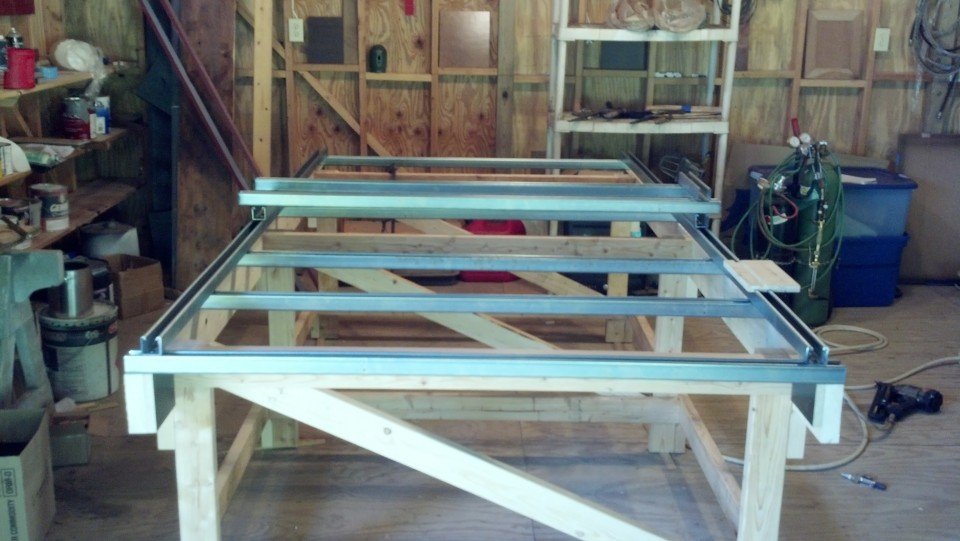
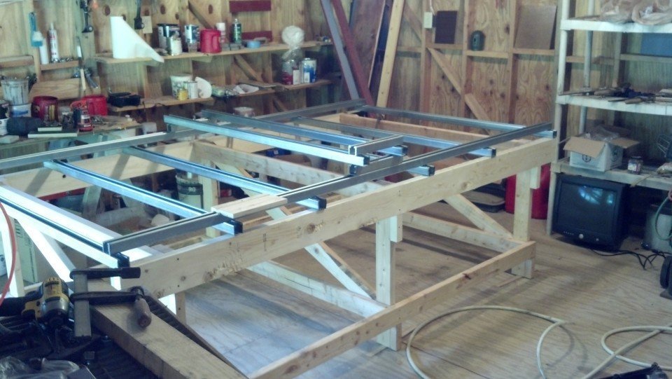
Out with the old..
So I am writing this update not to say the machine is finally done and the plans are posted, but to say that I think this design is not the one I am going forward with, it is too complicated, hard to put together, and really not the machine I hoped it would be. I know I could probably incorporate some of Paul’s changes and suggestions and make it better, but I think I have some up with something better. That being said, I do intend to release the plans I had been working on, I just need to get the file set in order and I will post it (no really).
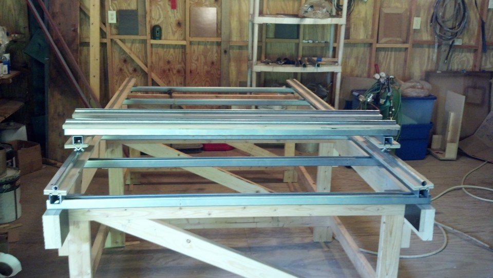
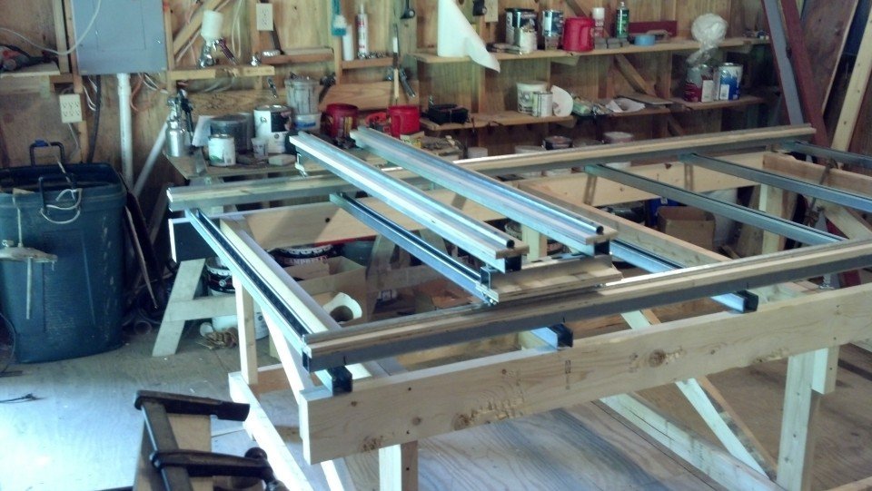
In with the new.
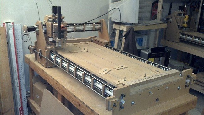
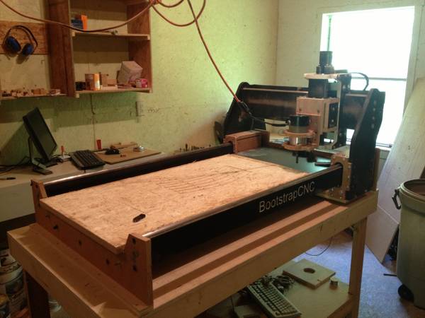
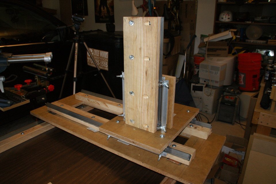
The concept I am working on is something you can just bolt to an existing table, in fact I went and picked one up at the local Goodwill to build the prototype on. It is sort of modeled after the early shop-bot concept.
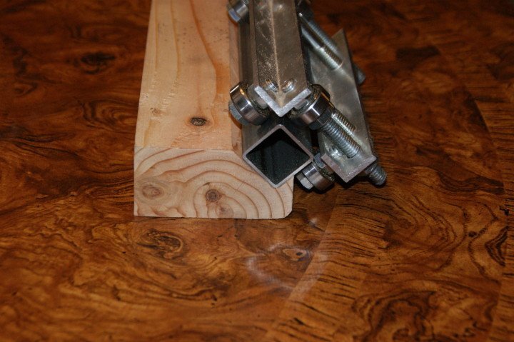
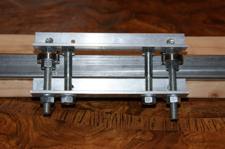
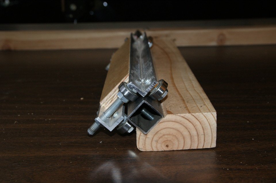
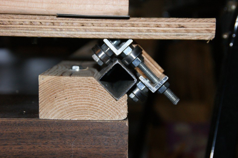
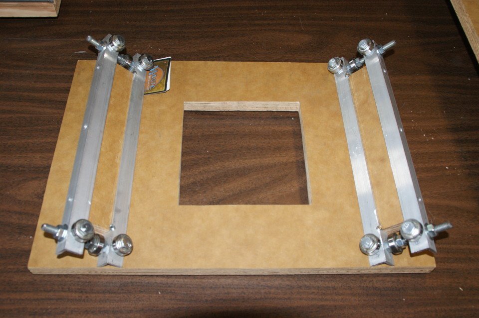
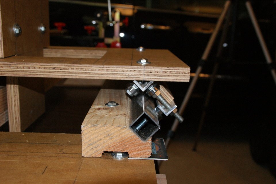
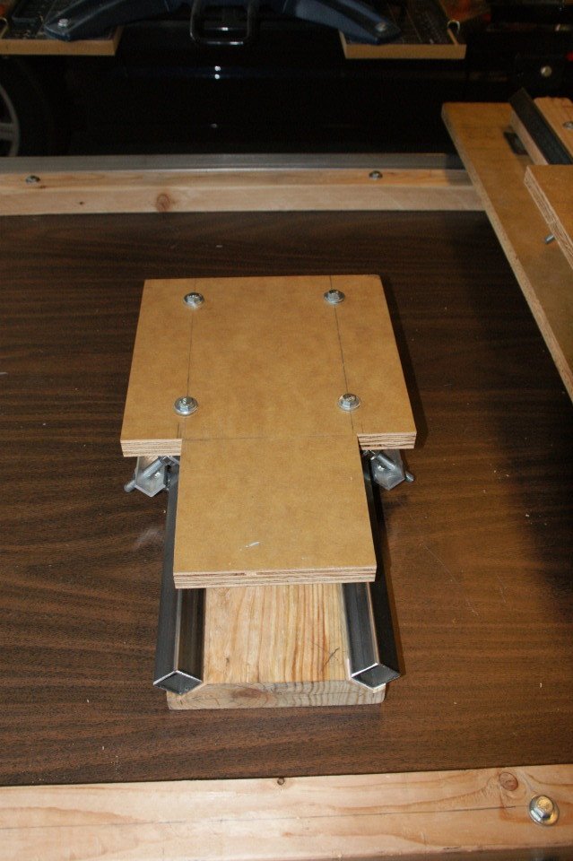
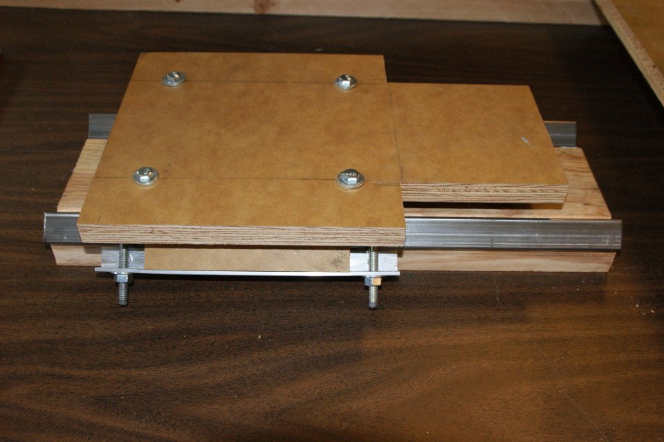
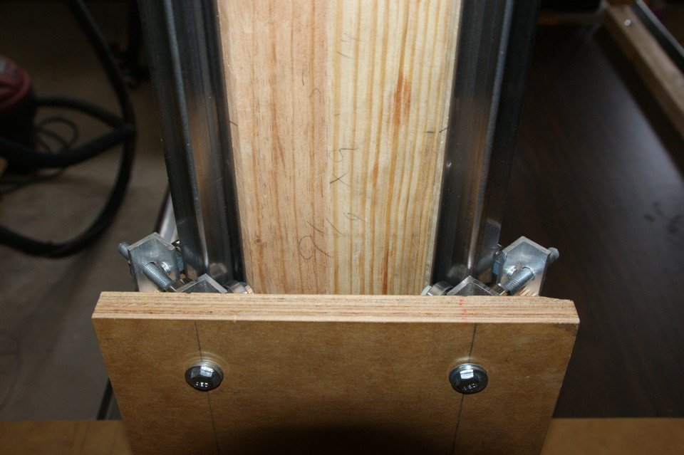
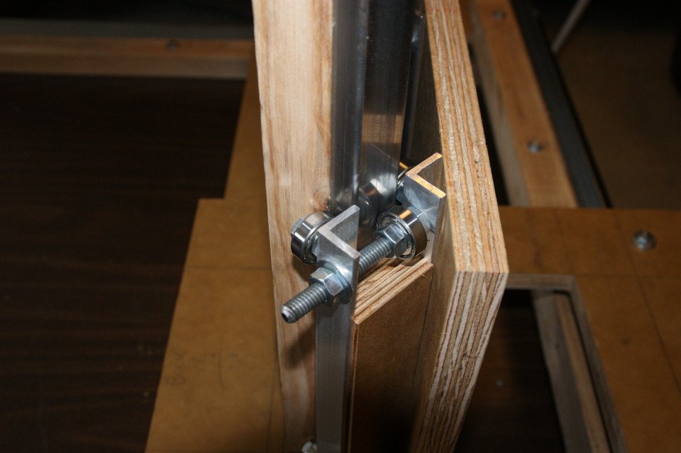
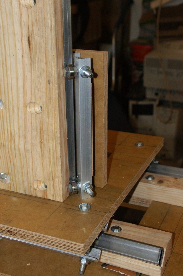
The bearing design is really the new element here, it rides on a single piece (per side) of 1″ square tubing mounted in a v-groove cut into a 2×4 piece of material (2×4 in the prototype). The bearing tension can be adjusted using a wench, and by using a pair mounted to flat piece of wood you can create an assembly that moves easily and does not lift of the rails.
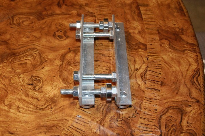
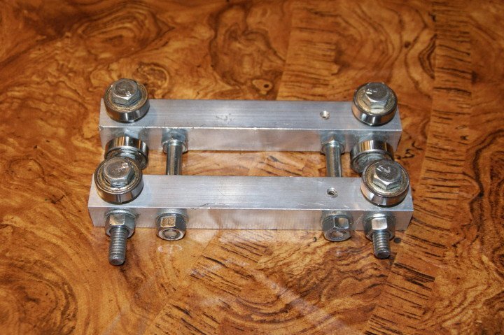
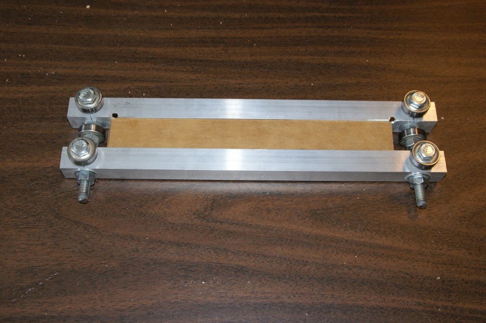
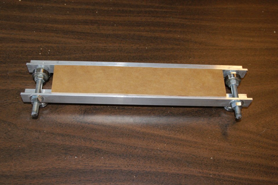
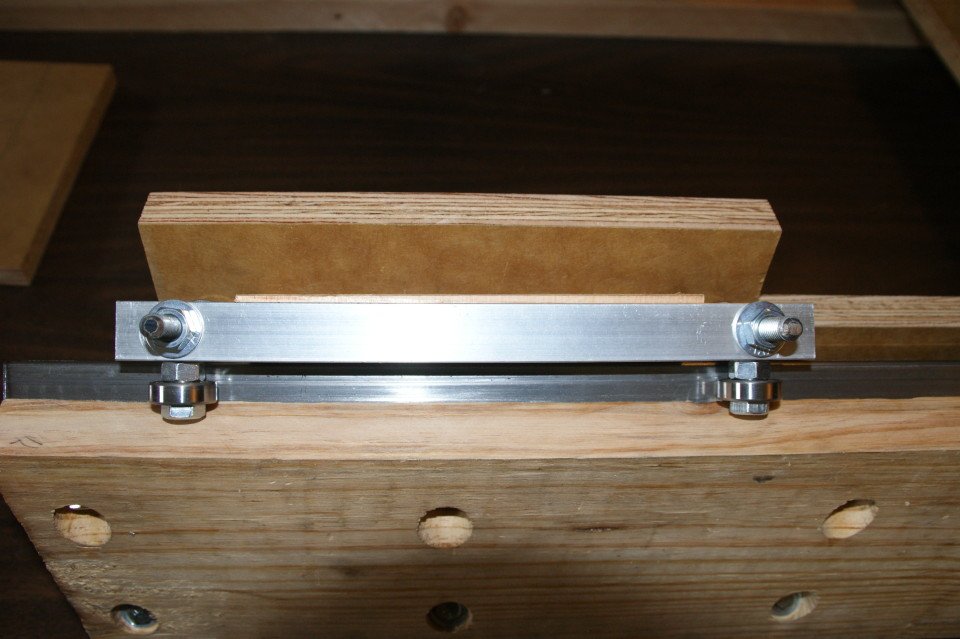
This is the first prototype built, I was using bolts to adjust the spacing between the top and bottom bearing but ended up replacing those with a piece of wood to simply things.


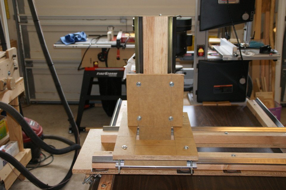
Once I was comfortable that it seemed likely to work, I did a little sketch up drawing and staring cutting parts out making modification on the fly as needed. My biggest concern was the Z-Axis and I originally thought I would build box type assembly and support the router with 2 sets of bearings (front and back), but after making one side of the prototype, I think 1 side should do just fine.
Here is a video version of this update that shows what I have built so far in action:
Further Video Updates:
I was thinking along the same lines! Have you tried them yet in actual use? I thought the “diamond” profile of the tube should be stronger and straighter than black pipe. Plus it is easier to drill into a flat surface then a round one.
I am about 2/3 the way thru my build with this bearing and it seems to be working well, hope to work on the Z axis next, then I should be able to finish it up and see if it works as well as I expect it to. Maybe 2 or 3 weeks before I have a working machine since work and family keep my out of the garage more than I’d like sometimes.
Thanks for this I think I will incorporate your bearing/rail design into my first diy machine. I think I will also stand up the Y axis mount one on top of the other which will allow more space. I found some great sketch up cnc models by the way on trimble 3d warehouse. I hope to make a narrower version of this one (2×8) with your bearing rails. http://sketchup.google.com/3dwarehouse/details?mid=92b8358ab0b83e1f3f222a37719e9945&prevstart=36
Cheers,
Brian
Cool, let me know how it works out… if you plan on blogging it let me know where, I’d love to see how it goes. I have looked at that design in the 3d warehouse (as well as others) a lot of good ideas there. I have a number of machine ideas in my head and I have been playing around with different rail configurations for the Y axis. Take a look at my shared Google drive folder here: CNC Prototype 2013, in particular look at sqaurerail_variations.skp, and sqaurerail11.skp.
So far the easiest way I have found to create the rail is to cut a 2×3 piece with a 45 degree angle and then route a 1″ channel into it, see DSC00044.JPG and DSC00047.JPG.
Happy building,
Don B.
Hi! I really like your design. How are you doing with the development? I am wondering how and where you attach the spindles to drive this construction. Can you tell/show me more?
Hello ! I’m so very impressed with your ingenious bearing design. I’m new to CNC and about 90 % done on building an MDF machine from the buildyourowncnc website plans. As I’m putting the finishing touches on that machine I can already see its liminations relating to the rails not being able to be adjusted… it seems to be just about the number one complaint from builders of that design. For my hobbyist purposes your new design seems to be ideal and a wonderful challenge to attempt. I do have one quick question though. How did you cut the v-grooves on the 2×4’s. Was that done on a table saw ?… Best regards and much success on your build. Thanks in advance.
Thanks for the kind words.
I cut the v-grooves on the table saw… was a little bit scary. So far the easiest way I have found to create the rail is to cut a 2×3 piece with a 45 degree angle and then route a 1″ channel into it, see DSC00044.JPG and DSC00047.JPG.
Take a look at my shared Google drive folder here: CNC Prototype 2013
For me, these rails/bearings have worked well so far, but that may be linked to the overall design and might not work as well on a different setup.
Good luck with your build, let me know if you have any questions or updates.
Sorry for missing this question for so long… My spindle/router mount is made from 1″ composite decking, 2 rectangles with a spindle sized hole in the middle of them (used a large forstner bit), then cut in half and edge drilled to allow 2 pieces of all threaded rod to pass through. The all threaded rod screws into tee-nuts in the z-axis plate, the mounts slide over them and are tighten around the router with hex nuts and washers. I have 2 sets of mounts holding the router, one might have been ok, but more is better :).
Here are a few pics… Let me know if you still have questions.
Thanks for answering my question on youtube, What motors and couplings are you using for this model?
I’m new to the CNC issue and I want to build one
hi again, i cant see your “Google drive folder CNC Prototype 2013”
Sorry, I updated the links so they should work now.
I am reusing motors and couplings from a previous build, the motors are Xylotex 270oz and the couplings are from DumpsterCNC. I have also used solid metal couplings from ebay with out issue.